Table of Contents
SVC Controller
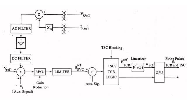
The block diagram of the basic SVC Controller incorporating a voltage regulator is shown in Fig. This shows that both voltage (VSVC) and current (ISVC) signals are obtained from potential and current transformers and fields. The AC filter is a notch filter to eliminate the signal component of a frequency corresponding to the parallel resonance in the system viewed from the SVC bus. The line capacitance (in parallel with SVC capacitance) can result in parallel resonance with the line inductance.
The SVC voltage regulator tends to destabilize this resonant mode of oscillation and the notch filter aims to overcome the problem. Any parallel resonance mode (of frequency below the second harmonic) can adversely interact with the regulator. if series capacitors are used along with SVC, then they can cause parallel resonance with a neighboring shunt reactor. If the second (parallel resonance) mode has a lower frequency (say below 20 Hz) a high pass filter in addition to the notch filter has been suggested.

The rectified signal is filtered. The DC side filters include both a low pass filter (to remove the ripple content) and notch filters tuned to the fundamental and second harmonic components . The notch filters are provided to avoid the adverse interactions of SVC caused by the second harmonic positive sequence and fundamental frequency negative sequence voltages on the SVC bus. For example, second harmonic positive sequence voltages at the SVC bus cause a fundamental frequency component in the rectified signal that results in the modulation of SVC susceptance at the same frequency.
This in turn (due to amplitude modulation) results in two components at sideband frequencies (0, 2f) in the SVC current. The DC component can result in unsymmetric saturation of the SVC transformer and the consequent increase in the magnetization current containing even harmonics.
It has been observed that this adverse harmonic interaction between the SVC and the network can result in a large distortion of the SVC bus voltage and impaired operation of SVC (termed as second harmonic instability).
The Susceptance Regulator aims to regulate the output of SVC in the steady state such that the full dynamic range is available during transient disturbances. The output of the Susceptance Regulator modifies the voltage reference Vref in a steady state. However, its operation is deliberately made slow such that it does not affect the voltage regulator function during transients.
In contrast to the Susceptance Regulator, the Supplementary modulation Controller (SMC) is designed to improve the performance of SVC during transient conditions and not affect the steady state. SMC has control input using appropriate signals obtained from local measurements and provides a limited output at either the summing junction before or after the voltage regulator. Thus, it modulates either the SVC bus voltage or susceptance directly to dampen oscillations and improve stability.
Protective Functions of SVC Control
The SVC control also has functions to protect faulted or overloaded conditions that may affect the equipment or system response. These are listed below :
- Undervoltage Strategy
- TCR Overcurrent Limiter
- SVC Control Interactions at Subsynchronous Frequencies
1. Undervoltage Strategy
The SVC is ineffective under low voltage conditions due to faults in the system. However, clearing the fault can result in temporary overvoltages due to load rejection, particularly under weak system conditions. The response of the SVC required immediately after the fault clearing is opposite of the normal voltage regulator function during a fault. To avoid delay in the necessary response of the SVC, the normal voltage regulator action is deactivated when the voltage falls below a threshold (say 60% of the normal voltage ).
TSC is blocked and BrefSVC is frozen at the previous value (before the voltage dip). The normal SVC regulator action is resumed after the voltage climbs above a certain threshold (say 70%) and remains (above the threshold for some time (say 30 ms). The blocking of TSC also helps in reducing the transient by preventing the capacitor discharge.
2. TCR Overcurrent Limiter
Under high voltage conditions, the SVC will be at its inductive limit, and the TCR current may exceed its rated value. To protect the thyristor valves used in TCR, it is necessary to limit the current through it by phase control. To avoid interaction with the voltage regulator function, a time delay is introduced
(of the order of 100 ms). The overcurrent limiter takes into account the short-term overload capability of the TCR.
3. SVC Control Interactions at Subsynchronous Frequencies
The SVC voltage regulator can adversely affect the damping of the sub-synchronous frequency torsional modes due to turbine-generator rotors and elastic shafts (constituting a lightly damped mass-spring-damper system). Unlike fixed series capacitors, the Torsional Interaction (TI) problem with SVC is insignificant. It has been suggested that using a low pass filter or Transient Gain Reduction (TGR) in conjunction with the voltage regulator is adequate to overcome the problem .
Frequently Asked Questions (FAQs)
-
What is the purpose of the SVC?
An SVC is a device that automatically adjusts power to make the system more efficient. It’s used in two ways: on power lines to control voltage (transmission SVC) or near large factories to improve power quality (industrial SVC).
-
What are the different types of SVC?
The SVC (Static Var Compensator) can work in two modes :
1. Voltage regulation mode: It adjusts the voltage within set limits.
2. Var control mode: It keeps the SVC’s power flow constant. -
What is the control system of SVC?
An SVC adjusts power to keep the bus voltage at the right level. If the voltage drops, it adds more reactive power to raise it. If the voltage goes up , it reduces the power or absorbs more, bringing the voltage back to the desired level.


Leave a Reply