Table of Contents
Stepper Motor
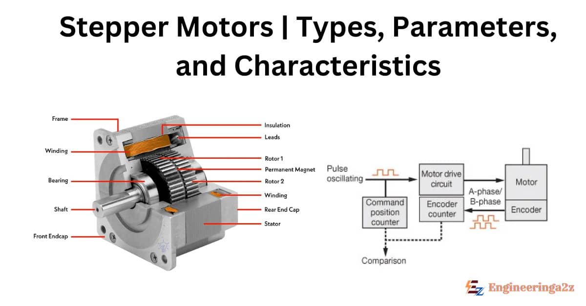
Stepper motors convert electrical pulses received by their excitation (control) windings into discrete angular displacements-commonly called as steps. In fact, they function as decoders, transforming the digital information received in the form of electrical pulses into steps of angular position. Since there is a direct correspondence between the number of input pulses and the number of discrete angular steps taken by the motor, there is no need for a feedback transducer for measuring the angular position of the rotor. This means that automatic control systems can be built without feedback using stepper motors as actuators.
Stepper motors are widely used in numerically controlled (NC) machine tool positioning systems, since:
- (i) The command signal in NC systems is in the form of numerical code or pulses derived from magnetic tape or punched paper and a stepper motor can operate directly off such command signals without requiring expensive analogue/digital (A/D) and digital analogue (D/A) converters,
- (ii) There is no need for a feedback transducer, which is quite cumbersome to instal on machine tools and,
- (iii) The open loop system does not pose stability problems, thereby, considerably simplifying the system design.
Types of Stepper Motor
The Stepper Motor is either of the permanent magnet type or the variable reluctance type, let us discuss both of them in detail given below:
1. Stepper Motor with Permanent Magnet Rotors
The rotor made out of permanent magnet material is either of the salient pole or cylindrical type. The stator has a two or three or four phase winding located in a slotted structure. The number of slots per pole per phase is usually chosen as one in multipolar machines.
A schematic representation of a 2-pole, 2-phase permanent magnet stepper motor is given below which is capable of making discrete steps of 90° as soon as voltage pulses are applied to the two phases of the exciting winding in a specified sequence. The axis of the magnetic field can have four different positions corresponding to the two different directions of flow of current in phases A and B of the exciting winding.

- (i) Current is directed from the ‘start’ to ‘finish’ of Phase ‘A’ while Phase B’ carries no current.
- (ii) Current flows from the ‘start’ so ‘finish’ of Phase ‘B’, while Phase ‘A’ doesn’t carry any current.
- (iii) Current is directed in Phase ‘A’ from ‘finish’ to ‘start’, with no current in Phase ‘B’, and
- (iv) Current passes through Phase ‘B’ from ‘finish’ to ‘start’, with no current in Phase ‘A’.
2. Variable Reluctance Stepper Motors
The rotor is made out of slotted steel laminations and has no winding in it. The stator is usually wound in three phases. The stator windings are excited with the help of an external logic circuit in a specified sequence and the rotor seeks that position in which the reluctance between the stator and rotor is a minimum. The figure shows a schematic representation of a variable reluctance stepper motor having six salient poles (teeth) with concentrated exciting windings around each one of them.

The coils wound around diametrically opposite poles are connected in series and the three circuits (Phases), thus formed, are energized from a d.c. source through an electronic switching device. The rotor has two salient projections only. When coil A – A’ is excited the rotor is subjected to an electromagnetic torque and rotates until its axis coincides with the axis of the mmf set up by phase A. Next, when coil BB’ is also excited, the rotor moves in the clockwise direction and takes up the minimum reluctance position shown in Fig., thereby moving an angular distance of 30°.
You may also like
Now, coil A – A’ is disconnected from the supply, keeping coil B – B’ excited. Then, the rotor moves through a further step of 30° and takes the position indicated in Fig. By successively exciting the three phases in the above manner, the motor takes twelve steps to make one complete revolution.
Stepper Motor Parameters
The most important parameters of stepper motors are as follows :
- Step angle, defined as the angular displacement of the rotor in response to each pulse,
- Critical torque represents the maximum load torque at which the rotor does not move when an exciting winding is energized,
- Limiting torque, defined for a given pulsing rate or stepping rate measured in pulses per second, as the maximum load torque at which the motor follows the control pulses without missing any step,
- Synchronous stepping rate defined as the maximum rate at which the motor can step without missing steps. The motor can start, stop, or reverse at this rate.
- Slewing rate, is defined as the maximum rate at which the motor can step unidirectionally. The slewing rate is much higher than the synchronous stepping rate, but the motor will not be able to stop or reverse without missing steps at this rate.
Stepper Motor Characteristics
Torque-displacement characteristic gives the relation between the electromagnetic torque developed and the displacement angle 9 of the rotor from its stable equilibrium position during steady state with one control winding permanently energized. This torque is obviously zero for the equilibrium position, i.e., at 00 with respect to the poles of the energized winding. An opposing electromagnetic torque appears as soon as an effort is made to move the rotor from this position.
Initially, this torque increases with the angular displacement reaching a maximum value and, then, falls to zero. The nature of the variation torque versus displacement is almost sinusoidal for motors with both permanent magnet rotor and variable reluctance rotor as shown in Fig. Actually, they correspond to the torque-angle characteristics of a conventional cylindrical rotor synchronous motor and reluctance motor respectively.
The torque developed is proportional to sin e for the former motor type and sin 20 for the latter. Whereas the permanent magnet rotor has its maximum torque, when the excitation is shifted 90°, the variable-reluctance rotor has zero torque for 90° shift and can move in either direction. The permanent magnet rotor has the significant feature that the rotor position θ is defined by the winding currents without any ambiguity; the variable-reluctance rotor has two possible positions for each winding current pattern.

Frequently Asked Questions (FAQs)
What is a stepper motor used for?
Stepper motors are commonly used in devices like floppy disk drives, scanners, printers, plotters, slot machines, CD drives, smart lighting, camera lenses, CNC machines, and 3D printers.
Is the stepper motor AC or DC?
A stepper motor runs when a DC voltage is applied to it through a driver.
Are stepper motors 12v or 24v?
Stepper motors often use bipolar “chopper” drives at much higher voltages, typically starting from 12V, with 24V, 48V, and 80V for control systems.
Related Posts
- Explain Construction and Working of Autotransformer
- Single Phase Induction Motor | Double Revolving Field Theory
- Draw and Explain the Construction and Working Principle of DC Motor
- Difference between Synchronous Motor and Induction Motor
- No load or Blocked Rotor Test on Three Phase Induction Motor
- Three Phase Induction Motor | Construction & Working Principle


Leave a Reply