Table of Contents
Introduction
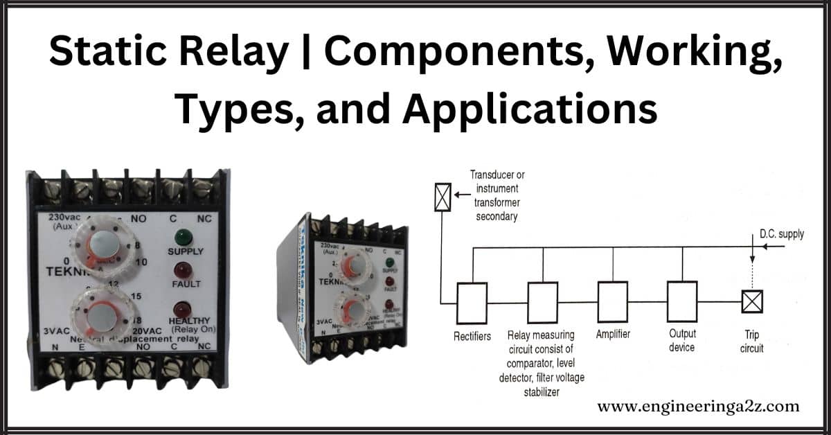
The solid-state relay, also known as a static relay, was introduced back in 1960. Unlike traditional relays, it doesn’t have any moving parts. This makes it more durable and faster in responding to signals. These relays use semiconductor devices like integrated circuits, transistors, and microprocessors instead of mechanical components.
Static relays essentially do the same job as older relays but with modern technology. They can handle various tasks without the need for mechanical parts.
What is a Static Relay?
A static relay is like an electric switch, but it doesn’t have any parts that move. Instead, it uses stationary components like magnetic and electronic circuits to control the flow of electricity. Unlike old-fashioned relays that rely on moving parts, static relays use electronic circuits to do the job.
Both types of relays are used to manage electrical circuits, deciding whether they should be on or off based on an electrical signal. Static relays work similarly to traditional ones but without any moving pieces. They’re designed with modern technology, like microprocessors and digital circuits, to control electricity more efficiently.
Components of a Static Relay
A static relay, also known as a solid-state relay, is an electronic device used to control electrical circuits. It’s a modern replacement for old mechanical relays, offering benefits like fast response times, durability, and low maintenance needs.
Here are the main parts of a static relay:
- Control Input: This is how the relay is turned on or off. It typically involves low-level electrical signals from devices like microcontrollers or sensors.
- Solid-State Switching Device: This is the heart of the relay, often made of semiconductor materials. It turns the electrical power to the device on or off.
- Isolation Barrier: It separates the control and load circuits to prevent electrical interference and ensure safety.
- Voltage and Current Sensing Circuits: These circuits monitor changes in voltage and current in the electrical system, helping to keep them stable.
- Protection Features: Static relays come with built-in protections like overcurrent, overvoltage, short-circuit, and thermal protection to keep the system and the relay itself safe.
- Status Indicators: These are displays, often LEDs or LCD screens, that show the relay’s operating status and any issues that arise.
- Interface Terminals: These are connection points for external wiring, allowing the relay to be easily integrated into the electrical system.
- Diagnostic and Communication Interfaces: Some advanced static relays offer interfaces like RS-485, Modbus, or Ethernet, enabling remote operation, monitoring, and diagnostics for increased reliability and easier maintenance.

Working Principle of a Static Relay
The working of Static relay is mentioned below:
- Input Signal: The relay receives an electrical signal, like current or voltage, from the system it’s monitoring.
- Signal Processing: The relay’s control circuitry checks the input signal against preset limits or conditions.
- Switching Decision: If the input signal meets certain criteria, the control circuit decides whether to turn something on or off.
- Output Action: Based on the decision, the relay’s electronic switch either lets electricity flow through or stops it, controlling the connected circuit.
Static Relay Types
There are different types of static relays which are discussed below.
- Electronic relays.
- Transductor relays.
- Transistor relays.
- Rectifier bridge relays.
- Gauss effect relays.
1. Electronic Relays
An electronic relay is like a fancy light switch that can turn things on and off without needing to physically move anything. It’s often used to control electrical circuits, like those in power lines, by opening and closing connections electronically instead of using mechanical parts.
When it comes to protecting transmission lines, electronic relays use a method called the current carrier pilot relaying method. This method involves using electronic valves, which are like special measuring tools, to keep an eye on the electrical current flowing through the lines and make decisions based on that information.
2. Transductor Relays
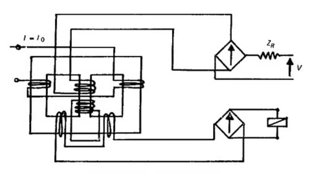
A Transductor Relay, also called a magnetic amplifier relay, is a type of relay that is simple in design and doesn’t have many moving parts. While some of them might be a bit more complex electrically, this doesn’t affect how reliable they are.
These relays rely on parts that don’t move, and their behavior is set beforehand and checked to make sure it works right. Because of this, they’re easy to design and test compared to older relays that have more mechanical parts.
They also don’t need much maintenance in practice, which means you don’t have to spend a lot of time or effort keeping them working well.

3. Transistor Relays
A transistor relay is a common type of static relay that uses transistors, which are electronic devices, to do the job. These relays use transistors like little switches and amplifiers to handle electrical signals.
The cool thing about transistor relays is that they can do a lot of different tasks. They’re not just limited to one specific job like some other relays. Instead, they can be adjusted to fit different needs and requirements.
Think of them as versatile tools that can be used in many different ways to control electricity in a circuit.
4. Rectifier Bridge Relays
Rectifier bridge relays are well-known because of advancements in semiconductor diodes. These relays typically consist of a moving iron or moving coil relay, along with two rectifier bridges.
The main feature of these relays is the use of rectifier bridges, which are circuits that convert alternating current (AC) to direct current (DC). The most common type of relay comparator used in rectifier bridge relays is based on these rectifier bridges. These comparators can be set up in two main ways: amplitude comparators or phase comparators.
In simpler terms, rectifier bridge relays use special circuits to control electricity flow, and they’re often used in systems where it’s important to compare electrical signals either in terms of their strength (amplitude) or their timing (phase).
5. Gauss Effect Relays
In Gauss effect relays, certain metals and semiconductors change their resistance when exposed to a magnetic field at low temperatures. This effect is known as the Gauss effect. It’s more pronounced when the ratio of depth to width increases. Some metals like bismuth, indium, and indium arsenide exhibit this effect at room temperature.
Gauss effect relays are preferred over Hall effect relays because they have simpler circuits and construction. However, in static relays, the Gauss effect is limited due to the high cost of crystals. As a result, there’s no need for polarizing current, and the output is higher compared to other types of relays.
Advantages of Static Relay
- These relays use very little power.
- They respond quickly and are very reliable, accurate, and durable.
- They don’t have any issues with heat buildup.
- They make input signals stronger, which makes them more sensitive.
- They’re less likely to trip accidentally.
- They’re very sturdy and can withstand shocks, making them suitable for areas prone to earthquakes.
- They require less maintenance.
- They respond very quickly.
- They’re resistant to shocks and vibrations.
- They reset quickly.
- They can operate for a very long time.
- They use very little power and can get power from a backup DC supply.
Disadvantages of Static Relay
- It’s easily damaged by high voltage surges, so precautions are necessary.
- The relay’s performance depends on the components used in its circuit.
- It can’t handle as much overload as other types of relays.
- It’s more expensive than electromagnetic relays.
- Its construction is easily affected by surrounding interference.
- It responds to sudden changes in voltage.
- It can’t handle short-term overloads as well as other types of relays.
- The relay’s performance can degrade over time due to component aging.
- Its speed is limited by mechanical properties.
- It’s not suitable for commercial use.
Applications of Static Relay
- Overcurrent Protection: Relays quickly detect if there’s too much current flowing through a system. If there is, they cut off power to prevent damage and keep the system running smoothly.
- Voltage Regulation: Static relays can adjust voltages to keep them within safe limits. They monitor voltage levels and adjust electricity flow to maintain good quality power for users.
- Load Shedding: When there’s more demand for power than the grid can handle, static relays prioritize critical loads and cut off power to non-essential ones to prevent system breakdowns and maintain stability.
- Fault Detection: Static fault relays are used to detect internal faults like short circuits or ground faults in power systems. They quickly identify problems and trigger protective actions to prevent damage and keep the system working properly.
Frequently Asked Questions (FAQs)
Is static relay used AC or DC?
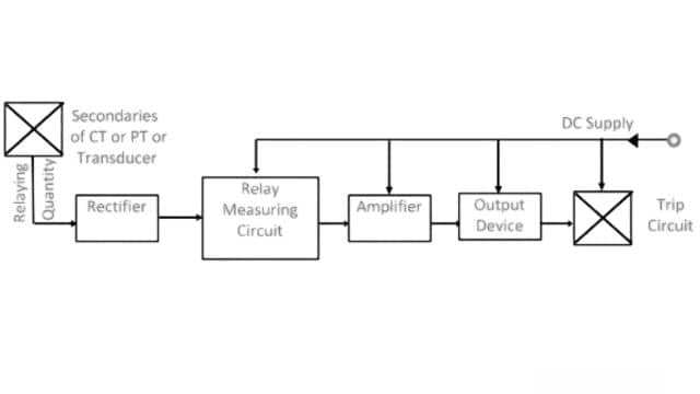
The rectifier converts AC to DC for the relay measuring unit. It then analyzes the signal level, magnitude, and phase by comparing them with available comparators.
What is the difference between a static relay and a mechanical relay?
Electromagnetic relays have moving parts, while static relays don’t. Both are used in lighting, automotive, robotics, and automation. They’re crucial for controlling circuits in various applications.
What is the function of a static relay?
Static relays respond quickly to prevent equipment damage and enhance system stability. They offer precise measurements of current, voltage, frequency, and power factor, ensuring reliable protection and control of power systems.
What is the work of static relay?
Mechanical relays use physical movements in contact circuits, while static relays rely on solid-state components like diodes and transistors, or digital logic circuits, without any moving parts.
Read Also:
- Relay | Construction and Working
- Electrical Cable | Components, Types and Application
- Distribution Systems | Classification and Challenges
- Transmission Line | Introduction, Classification, and Modelling
- Parallel Operation Of 1 Phase/ 3 Phase Transformers


Leave a Reply