Table of Contents
Introduction
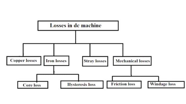
Electric machines transform energy. Motors change electricity into motion, while generators turn motion into electricity. During this process, energy isn’t perfectly converted; some is lost. These losses, like heat, reduce efficiency. In DC machines, losses occur as heat in the armature and field. There are five types: copper, brush, iron, stray, and mechanical losses.
Types of Losses in D.C. Machine
1. Copper Loss
Copper loss happens because of resistance in the DC machine’s winding. When electricity flows through the winding, it produces heat. This loss is related to the current and winding resistance and is calculated as I²R, where I is the current and R is the resistance. It’s called variable loss because it depends on how much the machine is used; more work means more loss.
In a DC machine, there are two windings: field and armature. Both have losses. The supply goes to the armature through carbon brushes, and losses occur due to voltage drop across these brushes.
i) Copper Loss in Armature Winding
The DC machine’s armature has very little resistance, which we call “Ra.” The copper loss in the armature is calculated as Ia²Ra, where Ia is the armature current and Ra is the armature winding resistance.
Armature copper loss = Ia2Ra
Most of the copper loss happens in the armature winding because that’s where the load current flows. This armature copper loss typically makes up around 25% to 30% of the total loss when the machine is running at full load.
ii) Copper Loss in the Field Winding
In a DC machine, the DC power supply is used to create the magnetic field in the field winding. The field winding has much higher resistance compared to the armature winding. Because of this, there is a significant copper loss in the field winding even when the field current is low. This copper loss in the field winding is calculated as If²Rf, where If is the field current and Rf is the field winding resistance.
The field winding’s copper loss typically accounts for about 20-25% of the total loss when the DC machine is operating at full load. This loss remains fairly constant because the field current and field resistance stays nearly the same in the DC machine.

2. Brush Contact Resistance Loss
In a DC machine, the armature rotates, and we use brushes to supply it with electricity. Ideally, we’d want the brushes to have no resistance when touching the commutator surface, but in reality, there’s always some resistance.
This resistance causes a voltage drop across the carbon brushes. The power drop in the brush is determined by this voltage drop (VBD) and the armature current (Ia).
So, you can calculate it as,
Power Drop in Brush (PBD) = VBD x Ia.
Where,
PBD = Power drop in Brush
VBD = Voltage Drop in Brush
Ia = Armature Current
3. Core Losses or Iron Losses in DC Machine
In a DC machine, the armature winding is wrapped around a magnetic core. This core links the magnetic field created by the field coil to the armature wires. Within the core, we experience two types of losses: hysteresis and eddy current losses.
These losses are sometimes called “constant losses” because they remain roughly the same regardless of the machine’s workload. In total, the core loss typically makes up about 20-25% of the total losses when the machine is running at full capacity.
4. Mechanical Loss in DC Machine
In a DC machine, the field part stays still, while the armature rotates on bearings. Heat is produced due to friction between the inner and outer parts of the bearing, causing energy loss.
Another loss is windage loss, which occurs because the air around the shaft resists the machine’s rotation. To overcome this air resistance, the DC machine needs extra power from the source, and this extra energy equals the windage loss. Windage loss goes up as the machine spins faster.
5. Stray Losses in DC Machine
Stray losses in a DC machine are challenging to pinpoint precisely. They result from various factors like short circuit currents during commutation and flux distortion. Typically, stray losses account for approximately 1% of the overall losses in a DC machine.
Efficiency of DC Machines
Efficiency in a DC machine is a measure of how effectively it converts electrical energy into mechanical energy (or vice versa in the case of a generator). It’s calculated using the following formula:
Efficiency (%) = (Output Power / Input Power) x 100
Where:
- Output Power is the useful mechanical power produced by the machine.
- Input Power is the electrical power supplied to the machine.

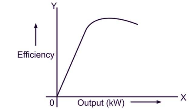
Efficiency tells you how well the DC machine is performing in terms of minimizing energy losses during the conversion process. A higher efficiency means less energy is wasted as heat, making the machine more effective in its operation.
Frequently Asked Questions (FAQs)
What are the losses and efficiency of DC machines?
DC machines have various losses: copper (I²R) losses in windings, core (iron) losses, brush friction, windage, and stray losses. Efficiency is typically around 85-95%, with losses causing energy conversion inefficiencies.
Why is DC less efficient than AC?
DC is less efficient than AC for long-distance power transmission because it requires expensive and less efficient conversion between AC and DC at both ends, resulting in higher energy losses.
Why is DC more efficient?
DC is more efficient than AC in some applications due to its lower energy losses in transmission lines and simpler conversion processes in devices like batteries and electronic components.
What is magnetic losses in DC machine?
In a DC machine, magnetic losses primarily refer to core losses, which include hysteresis and eddy current losses in the magnetic core material of the machine’s stator or armature. These losses occur due to the magnetic reversals and eddy currents induced in the core when the magnetic field changes direction as the armature rotates. Magnetic losses contribute to the overall energy losses and reduce the efficiency of the DC machine.
Read Also:
- Output Equation of an A.C. Machine
- DC Generator | Construction and Working Principle
- Three Phase Induction Motor | Construction & Working Principle
- Starting Methods of 3-Phase Induction Motor
- Computer Aided Electrical Machine Design Notes


Leave a Reply