Table of Contents
Adder
An adder is a digital circuit that adds two numbers together. Adders are used in the Arithmetic Logic Units (ALU) of many computers and other types of processors.
Types of Adder
It has mainly two types of adder :
- Half Adder
- Full Adder
1. Half Adder
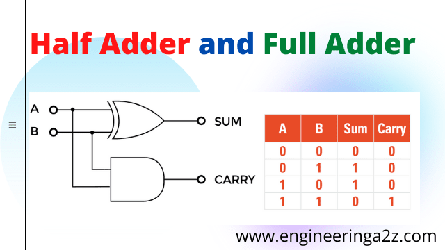
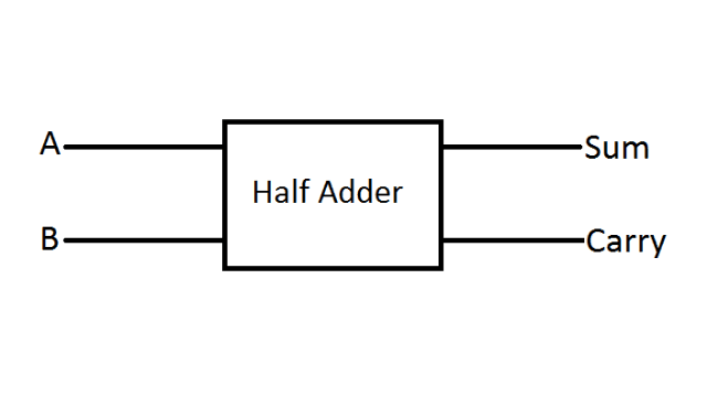
A combination circuit that performs the addition of two bits is called a half adder. The half adder accepts two binary digits at its input and produces two binary digits at its output, i.e., a sum bit and a carry bit.
The sum can be implemented using EX-OR gate and carry using AND gate.
Truth Table for Half Adder
| A | B | Sum | Carry |
|---|---|---|---|
| 0 | 0 | 0 | 0 |
| 0 | 1 | 1 | 0 |
| 1 | 0 | 1 | 0 |
| 1 | 1 | 0 | 1 |
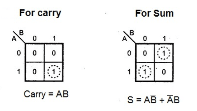
K-Map for Half Adder
Logic Diagram for Half Adder
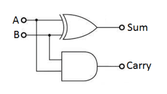
As the truth table shows that when both the inputs are different, the sum output is high otherwise it is low. The carry output is high when both the inputs are high.
2. Full Adder
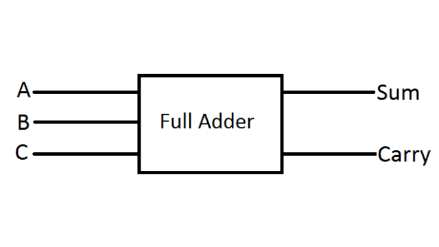
It is a combinational circuit which is used for adding three binary digits. So, a full adder accepts two input digits and an input carry digit and generate two outputs. The output is known as sum output and other output is carry output.
Truth Table for Full Adder
| A | B | C | Sum | Carry |
|---|---|---|---|---|
| 0 | 0 | 0 | 0 | 0 |
| 0 | 0 | 1 | 1 | 0 |
| 0 | 1 | 0 | 1 | 0 |
| 0 | 1 | 1 | 0 | 1 |
| 1 | 0 | 0 | 1 | 0 |
| 1 | 0 | 1 | 0 | 1 |
| 1 | 1 | 0 | 0 | 1 |
| 1 | 1 | 1 | 1 | 1 |
K-Map for Full Adder
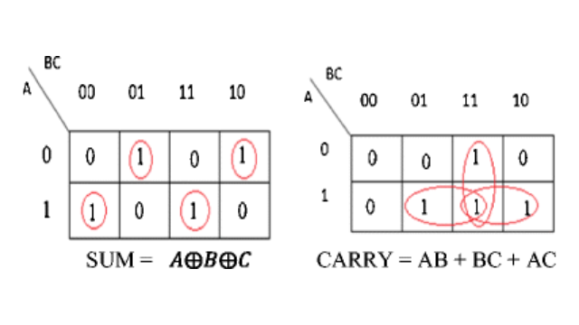
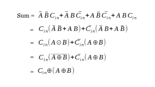
Logical Expression
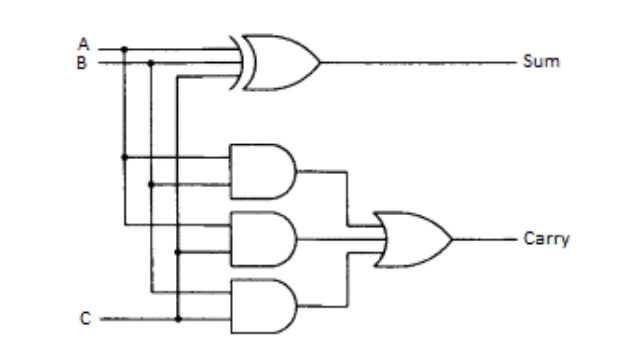
The logical expression for full adder is obtained from the truth table. Product of sum terms are taken whose output is one and it is given as :
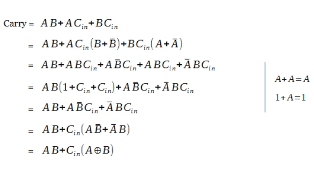
The logical expression for carry out is also obtained from truth table
Logic Diagram for Full Adder
Related Posts
- Travelling Wave Tube | Construction, Working and Applications
- Radar | Types of Radar, Advantages and Disadvantages
- Radar | Block Diagram, Working Principle and it’s Applications
- Multiple Access Techniques for Wireless Communication
- Internet of Things | Functional Block of IoT, Characteristics and Application
- Microphone | Types, Block Diagram, and its Working


Comments (1)
Thanks for any other fantastic post. The place else may just anybody get that type of information in such an ideal approach of writing?
I’ve a presentation subsequent week, and I am at the look for such
information.