Table of Contents
Electric Traction
The movement of vehicles by electrical energy is known as Electric Traction. In other words, driving force is obtained by Electric energy. The electrical input to the motors is received through overhead (O.H.) or underground distribution systems having substations. Both ac/dc systems are used.
The tramcars, trolleybuses, electric trains, etc., are examples of electric traction. Other examples are battery-driven vehicles and vehicles driven with a diesel engine and a motor generator set.
Different Electric Traction Systems
Different electric traction systems are described below:
1. DC System
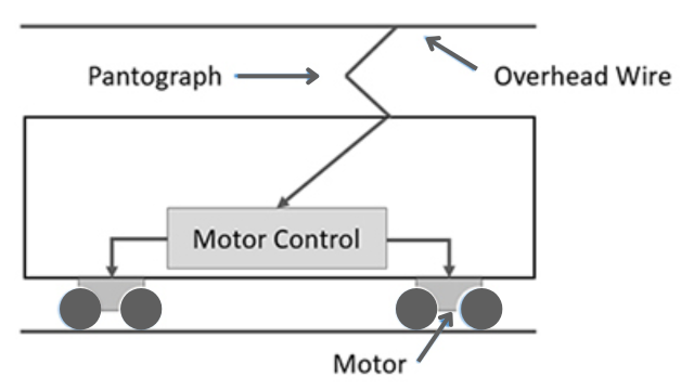
In this system, a DC series motor is used. The voltage used is 600 V for suburban areas. For the main line, the voltage used is between 2000 to 3000 Volts. The vehicles receive power from an O.H. distribution line and the steel track acts as a return conductor. The OH line receives power from substations. The substations receive power from three phases 33 KV line. This ac power is rectified by using rectifiers,
2. AC System
AC systems are widely used in traction systems due to their various advantages. These systems offer quick availability of alternating current (AC) power, which can be easily stepped up or down in voltage. AC motors used in these systems are also easy to control. Additionally, AC system requires fewer substations compared to other systems.
The ac traction system is of the following four types:
(i) Three-phase System: This system uses 3-phase slip ring motors. The advantage of this system is that Regenerative braking can easily be used. The voltage used is 3600 volts and the frequency is 16 Hz. This system is however not much in use.
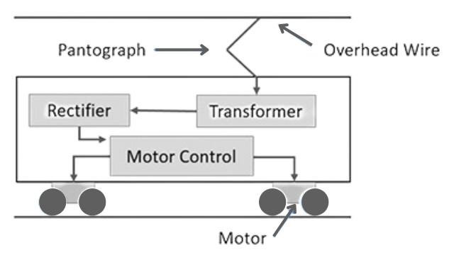
(ii) Single phase 50 Hz System: It has a single phase 25 KV 50 Hz line. The voltage is stepped down by the transformer and rectified in the locomotive itself and fed to DC series motors which provide tractive force. This system is very commonly used.
(iii) Single phase 16 Hz: This system is popular in some parts of the world.
In this single phase 15 KV, 16 Hz supply is used. This is stepped down and rectified to 400 V de in the locomotive. The single-phase ac series motors are used for tractive force. The disadvantage of this system is that substations are to be installed at 16 Hz.
(iv) Single phase to three phase System (Composite System) –This system is also called Kundo System.
The system uses a 16000 volts 50 Hz single-phase supply, which is converted into a three-phase system in the locomotive using a phase converter. The 3-phase supply is then given to 3-phase induction motor to obtain tractive force.
The three main types of electric traction systems that exist are as follows:
- Direct Current (DC) electrification system.
- Alternating Current (AC) electrification system.
- Composite system.
- Speed-time curve
Diesel Electric Traction
This system is designed to be cost-effective in areas where diesel fuel is readily accessible but coal and water resources are limited. It operates by using a diesel engine to power a generator, which in turn provides electricity to a traction motor. This eliminates the need for expensive infrastructure such as electrification and substations.
The characteristics of a diesel engine are as follows :
(a) Its torque is constant for various speeds.
(b) The HP increases with speed and
(c) It has a small overload capacity.
For traction work, the torque should be inversely proportional to the speed, therefore the constant torque of the diesel engine should be modified by a Torque converter to suit traction. This can be achieved by:
(i) Mechanical Transmission: In this, a variable gear is employed between the engine shaft and the driving wheel. This system is unpopular due to a lack of control facilities and flexibility.
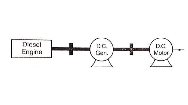
(ii) Electrical Transmission: This system employs a diesel engine coupled to a dc generator which supplies power to dc traction motors. Fig. shows the arrangement in diesel-electric traction.
The following types of Diesel-electric units are popular:
(a) Mainline diesel-electric locomotive containing the engine, up to 2000 H.P., and speeds up to 160 km/hr.
(b) Diesel-electric shunting locomotive containing diesel engine up to 500 HIP and speeds up to 60 km/hr.
(c) Diesel-electric multiple units (DMU) where each motor coach has an engine up to 200 HP. and speeds up to 110 km/hr.
(d) Diesel Electric rail, a car with an engine up to 600 H.P., which can operate as a single car or with one or more trailer coaches.
Speed-Time Curve
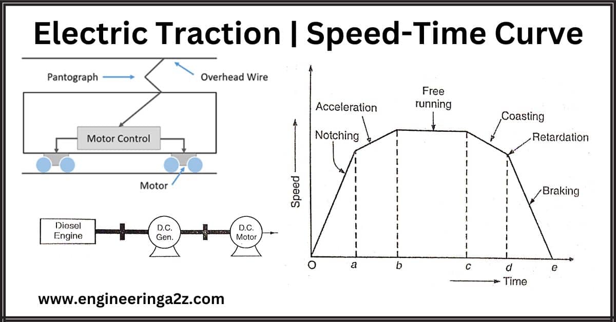
The curve drawn between speed (km per hr) and the time (in minutes or seconds) is called the ‘speed-time curve’. The speed time curve gives complete information regarding the movement of a train :
- The curve can give the speed of the train at any instant.
- The slope of the curve gives acceleration (or retardation).
- The area under the curve gives the total distance covered.
- The curve has the following parts as shown in Fig.
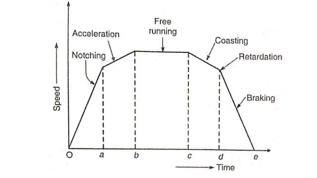
(i) OA: During this period, the traction motor accelerators from rest. This is known as the notching period. The current taken by the motor and the tractive effort is constant.
(ii) AB: During this period, the torque gradually decreases, and the speed increases, but the train still continues to accelerate. It is called the accelerating period. Finally, the train reaches a speed at which the tractive effort is equal to the resistance experienced by the train.
(iii) BC: During this period, the train runs at a constant speed. It is called the free-running period.
(iv) CD: During this period, the power is cut off and the train moves due to its kinetic energy. The train slows down due to retardation produced by friction. This is known as the coasting period.
(v) DE: During this period brakes are applied and the train is brought to a stop. This is called the braking period.
A simplified curve is shown in Fig.
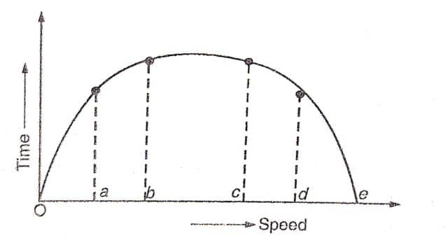
The value of acceleration or retardation should be such that there is no discomfort to the passengers. The acceleration at urban and suburban services is up to 4 km/hour/ second. With trolley buses, it is up to 6.5 km/hour/second. The coasting retardation is about 0.16 km/hr/sec. Braking retardation is up to 5 km per hr per sec.
Characteristics of a good traction system
A good traction system should have the following characteristics:
- It should have a high starting torque.
- The locomotive should be compact enough to run on any route.
- It should have easy speed control.
- The equipment should be capable of taking overloads for short periods.
- The equipment should be economical.
- The system should cause minimum wear and tear.
- The braking should be such that minimum wear is caused.
- The system should not cause any interference with telecommunication lines.
Advantages of Electric Traction:
- Very good speed control is possible.
- It has the advantage of achieving rapid acceleration and retardation.
- Its repair and maintenance are simple.
- Electric equipment can take large overloads, for a short time.
- There is no danger of corrosion.
- Electric braking is much superior to mechanical braking.
- Vibrations are less.
- It does not pollute the atmosphere.
- The electrical energy required for lights and fans in the train can be directly from the lines and a separate generator is not required.
Disadvantages of Electric Traction
- The capital cost of electric traction is very high.
- Failure of supply paralyzes the complete system.
- In a.c. traction system telecommunication lines get interference.
- Electric vehicles can run only on electrified tracks whereas vehicles using other fuel can run on the road also.
Frequently Asked Questions (FAQs)
List any four advantages of electric traction?
1. It can start in no time, whereas a steam engine takes time to make steam.
2. Electric energy is cheaper and more economical.
3. It can handle more traffic.
4. It can be used in underground railways due to the absence of smoke.What is electric traction?
The movement of vehicles by electrical energy is known as Electric Traction.
What are the characteristics of electric traction?
1. The equipment should be economical.
2. The system should cause minimum wear and tear.
Read Also:
- Characteristics and Advantages of A.C. Over D.C. and Vice Versa
- Cathode Ray Oscilloscope (CRO) Construction & Working Principle
- DIAC | Construction | Working and V-I Characteristics
- High Voltage Direct Current (HVDC) Transmission
- Difference Between AC and DC Welding


Leave a Reply