Table of Contents
Chopper
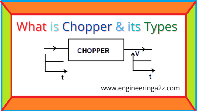
A chopper is a device which converts fix DC into variable DC. In a chopper circuit, a thyristor is used to switch ON supply to the load for certain intervals of time and switch OFF supply for another certain interval of time. The cycle of operation is repeated. The thyristor act as a high speed switch.

For turning ON the thyristor gate signal is applied and to turn it OFF, some method of forced commutation is applied. By varying the ON and OFF period, the voltage across load can be controlled.
Principle of Chopper Operation
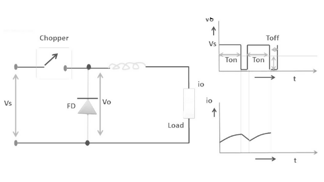
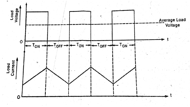
A chopper is a high-speed on/off semiconductor switch. It connects source to load and disconnects the load from source at a fast speed. During the period Ton chopper is ON and load voltage is equal to source voltage Vs. During the interval Toff . Chopper is off load current flows through the freewheeling diode (FWD). As a result load terminal are short circuited by FWD and load voltage is therefore zero during Toff in this manner a chopper dc voltage is produced at load terminals. During Ton load current rises whereas during Toff load current decays.
Choppers are of following two types:
- Step Up Chopper
- Step Down Chopper
1. Step up Chopper
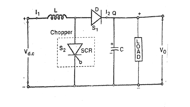
The chopper circuit in which output voltage is more than its input voltage is called Step up chopper. They are designed to give minimum output voltage equal to its input voltage. By changing the value of duty cycle the output voltage can be increased with finite limits.
When SCR is turned ON, the inductor current beings to rise linearly and energy is stored in the inductor. When SCR is turned OFF, the stored energy in inductor “L” is transferred to capacitor through diode “D” and then capacitor “C” stars charging resulting in the rise of of load voltage. The output voltage can be controlled by changing the Ton and Toff duration of the chopper.
2. Step Down Chopper
In step down chopper, the load voltage can be less than or equal to the source voltage and power flow from DC source to load.
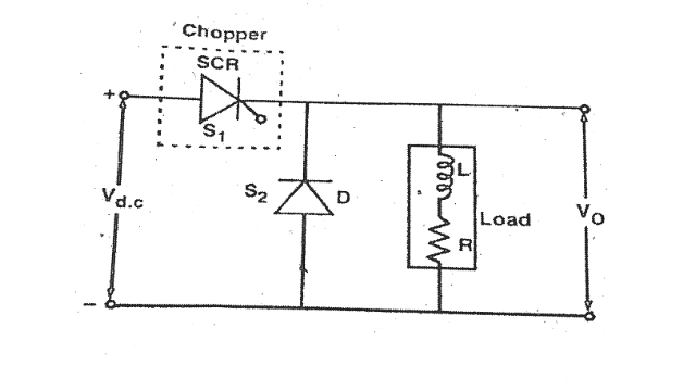
It is basically a series switch which can be turned ON and OFF at high frequency to get train of square pulses across the load. The SCR used in the circuit act like a switch; Diode connected across the load provides path for the inductive load current when SCR is open.
When SCR is not conducting, the voltage across load is zero. When SCR is turned on the load voltage is V0 = Vdc and load current arises exponentially.
Applications of Chopper
- Speed controllers for DC motors.
- Driving brushless DC torque motors or stepper motors in actuators.
- Solar and wind energy conservation.
- chopper circuits are used as power supplies in computers, electronics instruments.
- Regenerative breaking.
Frequently Asked Questions (FAQs)
How output voltage in a chopper can be controlled?
The output voltage can be controlled by following three methods :
1. Keeping Ton constant , varying Toff
2. Keeping Toff constant , varying Ton
3. Varying Ton/Toff ratio.What is the purpose of free wheeling diode used in chopper circuit?
Generally load is connected to chopper is inductive, therefore a free wheeling diode is connected across the load to keep the current flowing when thyristor is OFF.
What is the main purpose of chopper?
Chopper is a device which converts fixed D.C. into variable D.C. , it act as an electronic switch used in power control and signal applications.
What is duty cycle of a chopper?
It is given by the ratio of time for which the chopper remains ON and the Ton+Toff . The output voltage can be changed by changing the duty cycle.
α = Ton/Ton=Toff
Related Posts
- Bipolar Junction Transistor (BJT)
- MOSFET | Working Principle | V-I Characteristics & Applications
- Full Wave Rectifier | Definition, Types and Working
- Cathode Ray Oscilloscope (CRO) Construction and Working Principle
- Solar Cell or Photovoltaic Cell Construction and Working
- B.Tech – Electrical Engineering Previous Year Question Papers Download


Comments (5)
Very great content my dear friend.
Day by day my respect is increasing for your content.
Thanku very much for your appreciation….
Excellent content………🤗🤗
Thanks so much for your appreciation